Showing posts with label visualise. Show all posts

7 January 2020

Visualising Architecture: GraphML Charting Module Dependencies

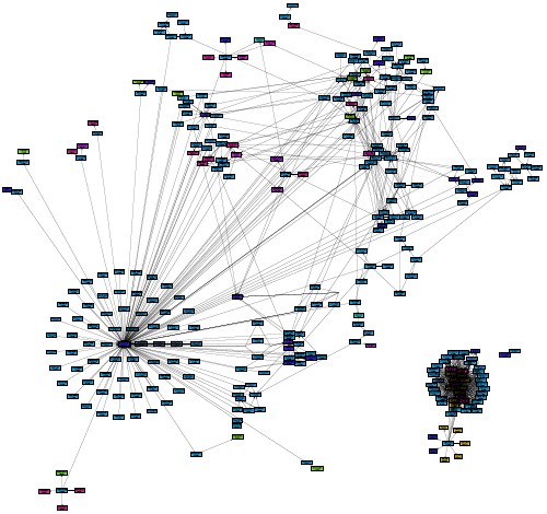
When working with existing code, analysing module dependencies helps me understand the bigger picture. For well defined modules like Eclipse OSGi or Maven there are tools to show all modules and their inter dependencies, e.g. the Eclipse Dependency Visualization tool or the Maven Module Dependency Graph Creator. For legacy technologies like COBOL and NATURAL - and probably some more platforms - we struggle due to the lack of such tools. Then the best approach is to extract the necessary information and put it into a modern, well known format. I wrote about such an approach in the past, e.g. loading references from a CSV into Neo4j for easy navigation and visualization. Today I want to sketch another idea I have used since many years: Using GraphML to chart module dependencies. For example, the following graph shows the (filtered) modules of a NATURAL application together with their dependencies in an organic layout.

Some modules of a NATURAL application in an organic layout, 2017
Process
GraphML is an XML-based file format for graphs. [...] It uses an XML-based syntax and supports the entire range of possible graph structure constellations including directed, undirected, mixed graphs, hyper graphs, and application-specific attributes. That should be more than enough to visualize any module dependencies. In fact I just need nodes and edges. My process to use GraphML is always the same:
  1. Start with defining or extracting the modules and their dependencies.
  2. Create a little script which loads the extracted data and creates a raw GraphML XML file.
  3. Use an existing graph editor to tweak and layout the diagram.
  4. Export the the diagram as PDF or as image.
Get the raw data
Extracting the module information is highly programming language specific. For Java I used my JavaClass class file parser. For NATURAL I used a CSV of all references which was provided by my client. Usually regular expressions work well to parse import, using or include statements. For example to analyse plain C, scan for #include statements (as done in Schmidrules for Application Architecture. Unfortunately there is not much documentation available about Schmidrules, which I will fix in the future.)

Create the XML
The next task is to create the XML. I use a little Ruby script to serializes a graph of nodes into GraphML. The used Node class needs a name and a list of dependencies, which are Nodes again. save stores the graph as GraphML.
require 'rexml/document'

class GraphmlSerializer
  include REXML

  # Save the _graph_ to _filename_ .
  def save(filename, graph)
    File.open(filename + '.graphml', 'w') do |f|
      doc = graph_to_xml(graph)
      doc.write(out_string = '<?xml version="1.0" encoding="UTF-8" standalone="no"?>')
      f.print out_string
    end
  end

  # Return an XML document of the GraphML serialized _graph_ .
  def graph_to_xml(graph)
    doc = create_xml_doc
    container = add_graph_element(doc)
    graph.to_a.each { |node| add_node_as_xml(container, node) }
    doc
  end

  private

  def create_xml_doc
    REXML::Document.new
  end

  def add_graph_element(doc)
    root = doc.add_element('graphml',
      'xmlns' => 'http://graphml.graphdrawing.org/xmlns',
      'xmlns:y' => 'http://www.yworks.com/xml/graphml',
      'xmlns:xsi' => 'http://www.w3.org/2001/XMLSchema-instance',
      'xsi:schemaLocation' => 'http://graphml.graphdrawing.org/xmlns http://www.yworks.com/xml/schema/graphml/1.1/ygraphml.xsd')
    root.add_element('key', 'id' => 'n1',
                     'for' => 'node',
                     'yfiles.type' => 'nodegraphics')
    root.add_element('key', 'id' => 'e1',
                     'for' => 'edge',
                     'yfiles.type' => 'edgegraphics')

    root.add_element('graph', 'edgedefault' => 'directed')
  end

  public

  # Add the _node_ as XML to the _container_ .
  def add_node_as_xml(container, node)
    add_node_element(container, node)

    node.dependencies.each do |dep|
      add_edge_element(container, node, dep)
    end
  end

  private

  def add_node_element(container, node)
    elem = container.add_element('node', 'id' => node.name)
    shape_node = elem.add_element('data', 'key' => 'n1').
      add_element('y:ShapeNode')
    shape_node.
      add_element('y:NodeLabel').
      add_text(node.to_s)
  end

  def add_edge_element(container, node, dep)
    edge = container.add_element('edge')
    edge.add_attribute('id', node.name + '.' + dep.name)
    edge.add_attribute('source', node.name)
    edge.add_attribute('target', dep.name)
  end

end
Layout the diagram
I do not try to layout the graph when creating it. Existing tools do a much better job. I use the yEd Graph Editor. yEd is a Java application. Download and uncompress the zipped archive. To get the final diagram
  1. I load the GraphML file into the editor. (If the graph is huge, yEd needs more memory. yEd is just an executable Jar - Java Archive - it can get more heap on startup using java -XX:+UseG1GC -Xmx800m -jar ./yed-3.16.2.1/yed.jar.)
  2. Then I select all nodes and apply menu commands Tools/Fit Node to Label. This is because the size of the nodes does not match the size of the node's names.
  3. Finally I apply the menu commands Layout/Hierarchical or maybe Layout/Organic/Smart. In the end it needs some trial and error to find the proper layout.
Conclusion
This approach is very flexible. The nodes of the graph can be anything, a "module" can be a file, a folder or a bunch of folders. In the example shown above, the nodes where NATURAL modules (aka files), i.e. functions, subroutines, programs or includes. In another example shipped with JavaClass the nodes are components, i.e. source folders similar to Maven multi module projects. The diagram below shows the components of a product family of large Eclipse RCP applications with their dependencies in a hierarchical layout. Pretty crazy, isn't it. ;-)
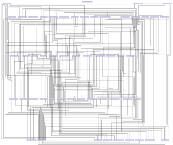
Components of an Eclipse RCP application in hierarchical layout, 2012

30 August 2019

Visualising Architecture: Neo4j vs. Module Dependencies

Last year I wrote about some work I did for a client using NATURAL (an application development and deployment environment using a proprietary language), for example using NATstyle, adding custom rules and creating custom reports. Today I will share some things I used to visualise the architecture. Usually I want to get the bigger picture of the architecture before I change it.

Industrial LegacyDependencies are killing us
Let's start with some context: This is Banking with some serious legacy: Groups of "solutions" are bundled together as "domains". Each solution contains 5.000 to 10.000 modules (files), which are either top level applications (executable modules) or subroutines (internal modules). Some modules call code of other solutions. There are some system "libraries" which bundle commonly used modules similar to solutions. A recent cross check lists more than 160.000 calls crossing solution boundaries. Nobody knows which modules outside of one's own solution are calling in and changes are difficult because all APIs are potentially public. As usual - dependencies are killing us.

Graph Database
To get an idea what was going on, I wanted to visualize the dependencies. If the data could be converted and imported into standard tools, things would be easier. But there were way too many data points. I needed a database, a graph database, which should be able to deal with hundreds of thousand of nodes, i.e. the modules, and their edges, i.e. the directed dependencies (call or include).

Extract, Transform, Load (ETL)
While ETL is a concept from data warehousing, we exactly needed to "copy data from one or more sources into a destination system which represented the data differently from the source(s) or in a different context than the source(s)." The first step was to extract the relevant information, i.e. the call site modules, destination modules together with more architectural information like "solution" and "domain". I got this data as CSV from a system administrator. The data needed to be transformed into a format which could be easily loaded. Use your favourite scripting language or some sed&awk-fu. I used a little Ruby script,
ZipFile.new("CrossReference.zip").
  read('CrossReference.csv').
  split(/\n/).
  map { |line| line.chomp }.
  map { |csv_line| csv_line.split(/;\s*/, 9) }.
  map { |values| values[0..7] }. # drop irrelevant columns
  map { |values| values.join(',') }. # use default field terminator ,
  each { |line| puts line }
to uncompress the file, drop irrelevant data and replace the column separator.

Loading into Neo4j
Neo4j is a well known Graph Platform with a large community. I had never used it and this was the perfect excuse to start playing with it ;-) It took me around three hours to understand the basics and load the data into a prototype. It was easier than I thought. I followed Neo4j's Tutorial on Importing Relational Data. With some warning: I had no idea how to use Neo4j. Likely I used it wrongly and this is not a good example.
CREATE CONSTRAINT ON (m:Module) ASSERT m.name IS UNIQUE;
CREATE INDEX ON :Module(solution);
CREATE INDEX ON :Module(domain);

// left column
USING PERIODIC COMMIT
LOAD CSV WITH HEADERS FROM "file:///references.csv" AS row
MERGE (ms:Module {name:row.source_module})
ON CREATE SET ms.domain = row.source_domain, ms.solution = row.source_solution

// right column
USING PERIODIC COMMIT
LOAD CSV WITH HEADERS FROM "file:///references.csv" AS row
MERGE (mt:Module {name:row.target_module})
ON CREATE SET mt.domain = row.target_domain, mt.solution = row.target_solution

// relation
USING PERIODIC COMMIT
LOAD CSV WITH HEADERS FROM "file:///references.csv" AS row
MATCH (ms:Module {name:row.source_module})
MATCH (mt:Module {name:row.target_module})
MERGE (ms)-[r:CALLS]->(mt)
ON CREATE SET r.count = toInt(1);
This was my Cypher script. Cypher is Neo4j's declarative query language used for querying and updating of the graph. I loaded the list of references and created all source modules and then all target modules. Then I loaded the references again adding the relation between source and target modules. Sure, loading the huge CSV three times was wasteful, but it did the job. Remember, I had no idea what I was doing ;-)

Querying and Visualising
Cypher is a query language. For example, which modules had most cross solution dependencies? The query MATCH (mf:Module)-[c:CALLS]->() RETURN mf.name, count(distinct c) as outgoing ORDER BY outgoing DESC LIMIT 25 returned
YYI19N00 36
YXI19N00 36
YRWBAN01 34
XGHLEP10 34
YWI19N00 32
XCNBMK40 31
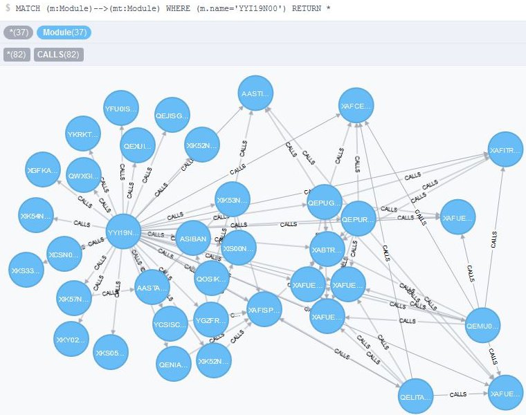
and so on. (By the way, I just loved the names. Modules in NATURAL can only be named using eight characters. Such fun, isn't it.) Now it got interesting. Usually visualisation is a main issue, with Neo4j it was a no-brainer. The Neo4J Browser comes out of the box, runs Cypher queries and displays the results neatly. For example, here are the 36 (external) dependencies of module YYI19N00:

Called by module YYI19N00
As I said, the whole thing was a prototype. It got me started. For an in-depth analysis I would need to traverse the graph interactively or scripted like a Jupyter notebook. In addition, there are several visual tools for Neo4J to make sense of and see how the data is connected - exactly what I would want to know about the dependencies.

2 October 2014

Visualising Architecture: Maven Dependency Graph

Last year, during my CodeCopTour, I pair programmed with Alexander Dinauer. During a break he mentioned that he just created a Maven Module Dependency Graph Creator. How awesome is that. The Graph Creator is a Gradle project that allows you to visually analyse the dependencies of a multi-module Maven project. First it sounds a bit weird - a Gradle project to analyse Maven modules. It generates a graph in Graphviz DOT language and an html report using Viz.js. You can use the dot tool which comes with Graphviz to transform the resulting graph file into JPG, SVG etc.

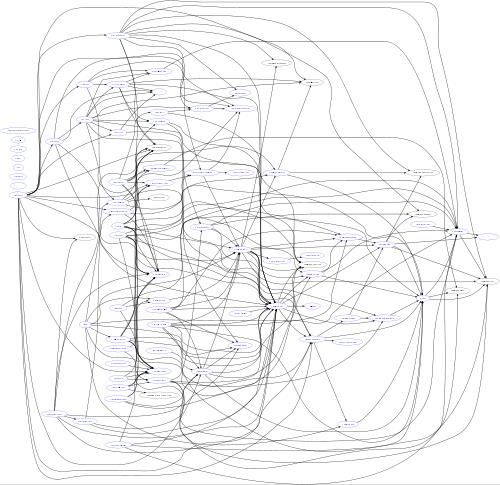
In a regular project there is not much use for the graph creator tool, but in super large projects there definitely is. I like to use it when I run code reviews for my clients, which involve codebases around 1 million lines of code or more. Such projects can contain up to two hundred Maven modules. Maven prohibits cyclic dependencies, still projects of such size often show crazy internal structure. Here is a (down scaled) example from one of my clients:

Maven dependencies in large project
Looks pretty wild, doesn't it? The graph is the first step in my analysis. I need to load it into a graph editor and cluster modules into their architectural components. Then outliers and architectural anomalies are more explicit.

15 November 2011

Visualising Architecture: Eclipse Plug-in Dependencies

In my job at the Blue Company I am working on a product family of large Eclipse RCP applications. Each application consists of a number of OSGi plug-ins which are the main building block of Eclipse RCP. There are dedicated as well as shared plug-ins. I am new to the project and struggle to understand which applications depend on which plug-ins. I would like to see a component diagram, showing the dependencies between modules, i.e. on OSGi level.

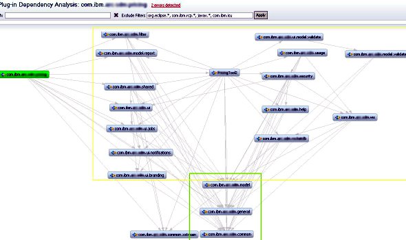
There is an Eclipse's Dependency Visualization tool inside the Eclipse Incubator project: Plug-in org.​eclipse.​pde.​visualization.​dependency_​1.0.0.20110531 which displays dependencies of plug-ins. This is exactly what I need. Here is the visualization of one of the products:

Plug-in Dependency Analysis
(The yellow and green bounding boxes were added manually and indicate parts of the architecture.) The tool's main use is to identify unresolved plug-ins, a common problem in large applications. While you find unresolved plug-ins by running the application, the tool helps even before the application is launched. For more information see this article on developerWorks about the use of the Dependency Visualization. The latest version of the plug-in, including its download for Eclipse 3.5.x, is available at the testdrivenguy's blog.